
Previously I had modified a digital safe to be controlled via an ESP8266; basically a WiFi safe.
I was asked if I could create a firmware for it that made it act like a timer safe; something along the lines of a Kitchen Safe.
I decided to take the opportunity to build (yet another) safe, using the combined esp/relay board. Without any soldering, I’m sure I can make a cleaner more reliable build!
Requirements
- A cheap Safe (Amazon link)
- An ESP8266 relay board.
- A 1N4001 Diode
- Cables
- Power Supply
The main relay board looks something like this
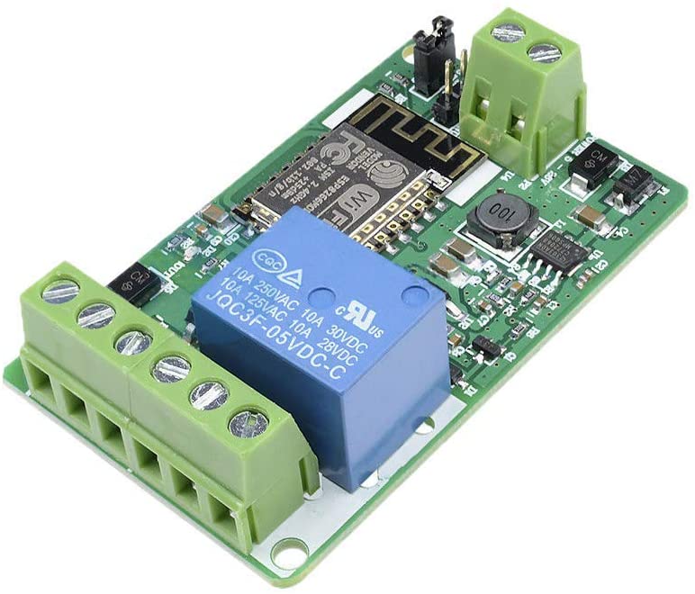
I’m not going to link to a seller, ‘cos sellers seem to change a lot. I’ve found searching “esp8266 hw-622” tends to find sellers.
This board comes in a couple of versions; the biggest difference is whether headers at the top left are present. I recommend getting them pre-installed because these boards don’t have USB connectivity; you program them using a 3.3V serial adapter connected to them.
The Safe
This time I picked a safe with a slot in the top. The normal idea is that the safe can be locked and then money added. It’s about $33. There’s a lot of similar models on Amazon.
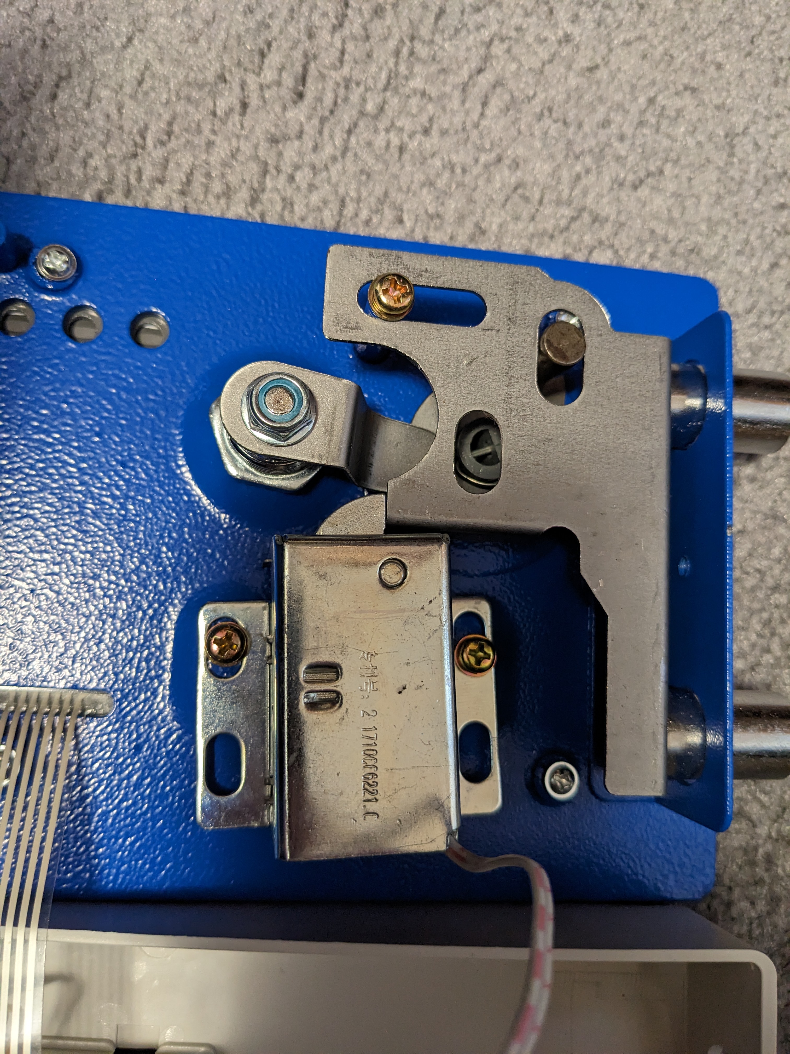
The internals on this safe are a little different to what I’ve seen before. Previously there was a simple plunger solenoid. This time the lock rotates.
In the locked position it looks like this.
When almost totally open we can see it’s rotated down out of the way
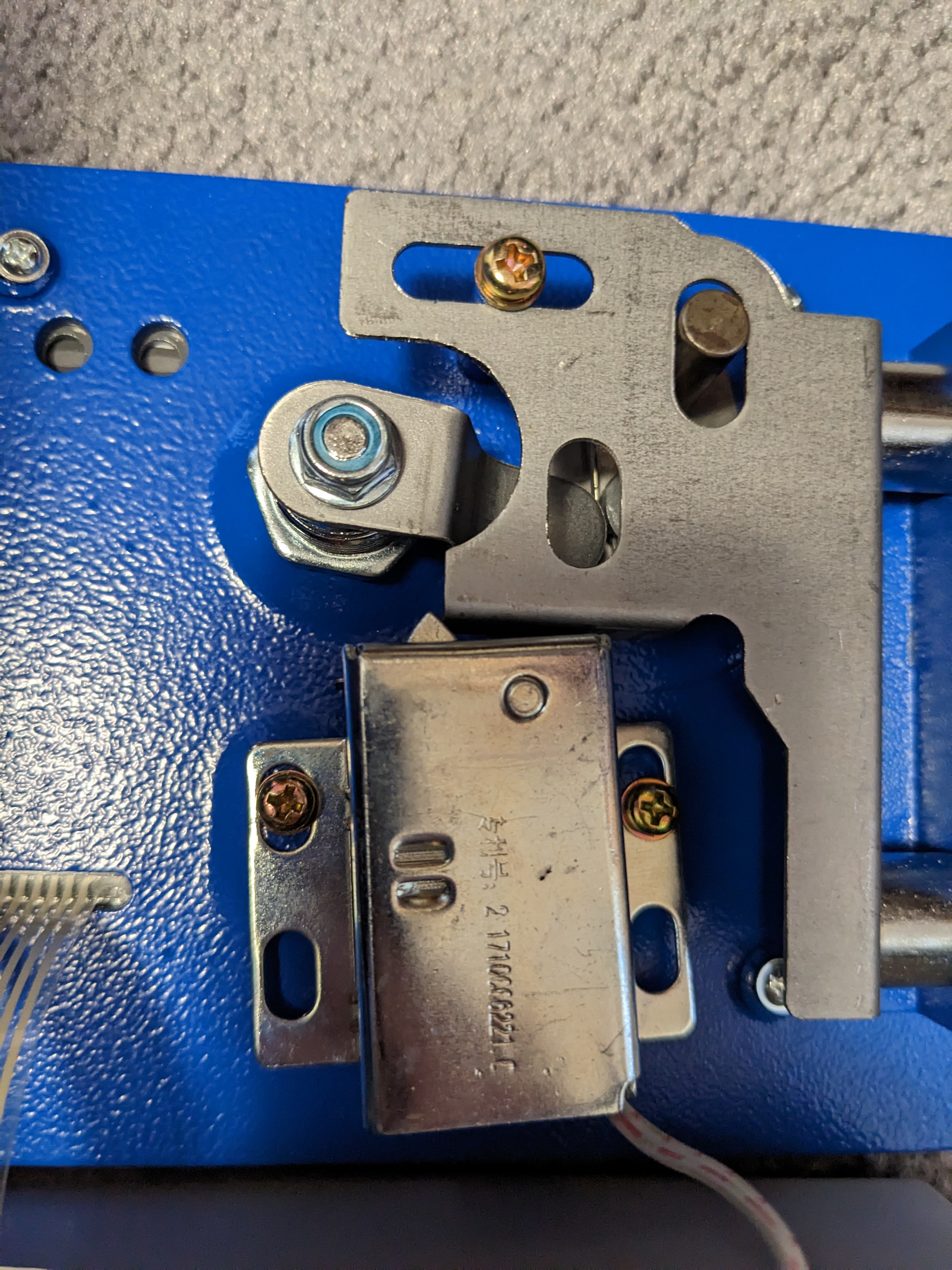
This would appear to fix a major issue of the previous design; the old one is susceptible to hitting it hard to send the plunger down, or even a strong magnet.
Of course the metal is still very thin so it’s not a high security safe!
Open the safe cover and disconnect the solenoid wire as we did in the v2 safe. I made a small hole in the door near the battery compartment so it can exit there. That’s it. That’s the only modification!
Put the cover back on.
At this stage I recommend programming the esp8266 with the safe software. It’s easier to get to the contacts.
It works just fine with the existing software
To do that we need to power it. So let’s talk about this. These boards can typically be powered from 7V up to 20V, if not higher. The power supply will also power the solenoid. I measured the coil at 18 ohms, so I think any power supply 500mA or higher would do; maybe call it 750mA for safety?
Now I had some spare 2.1mm x 5mm power pigtails spare.
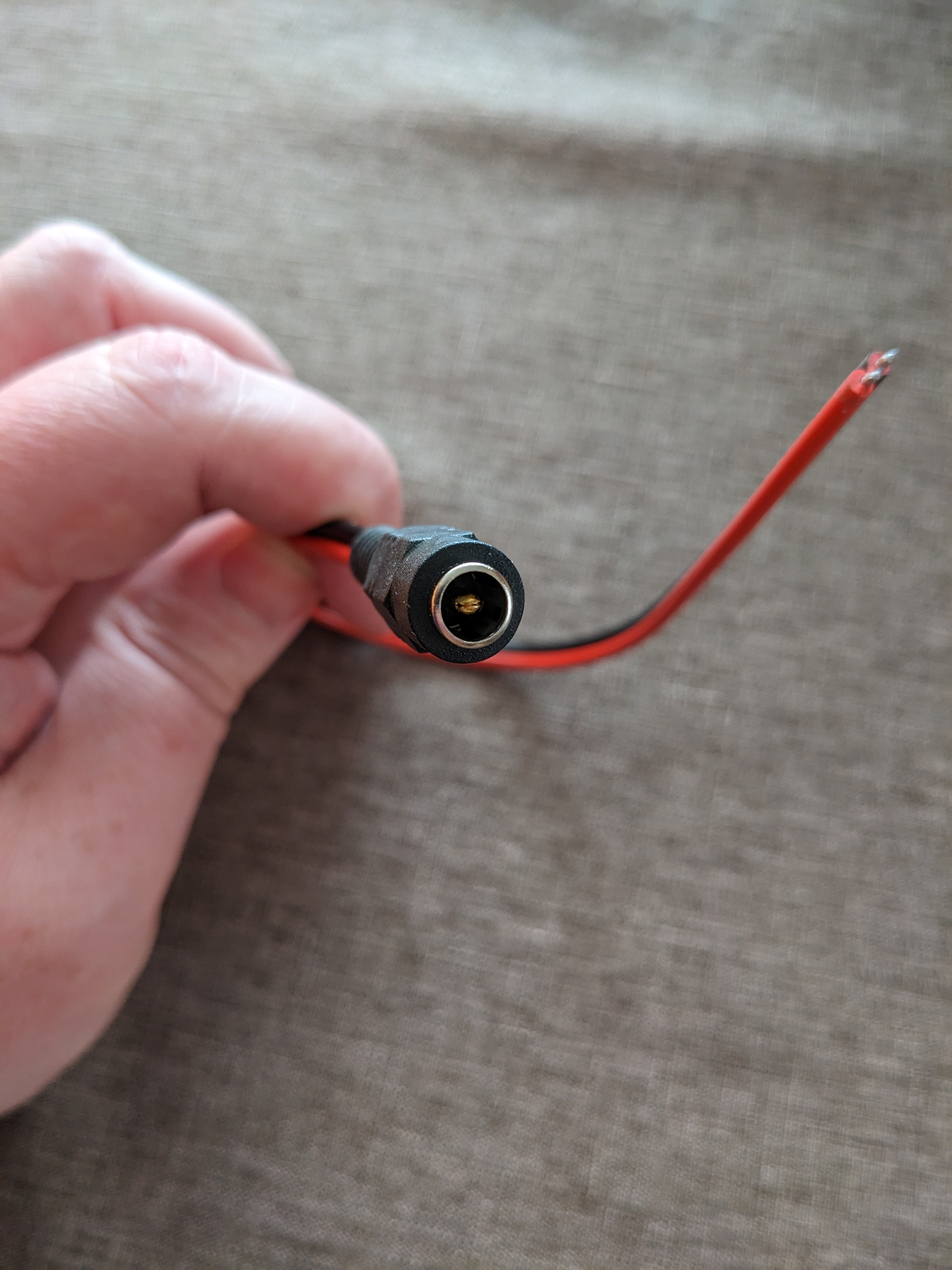
These aren’t optimal for this job because they’re not designed for “panel” work, but they do the job.
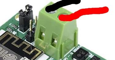
Connect the red wire to the right side, and the black to the left
Now you can program it using the Arduino software and your 3.3v serial adapter.
Hook it up to your network and test the safe software works. You’ll hear the relay clicking. Remember to change the configuration so it uses “4” (GPIO4) as the trigger.
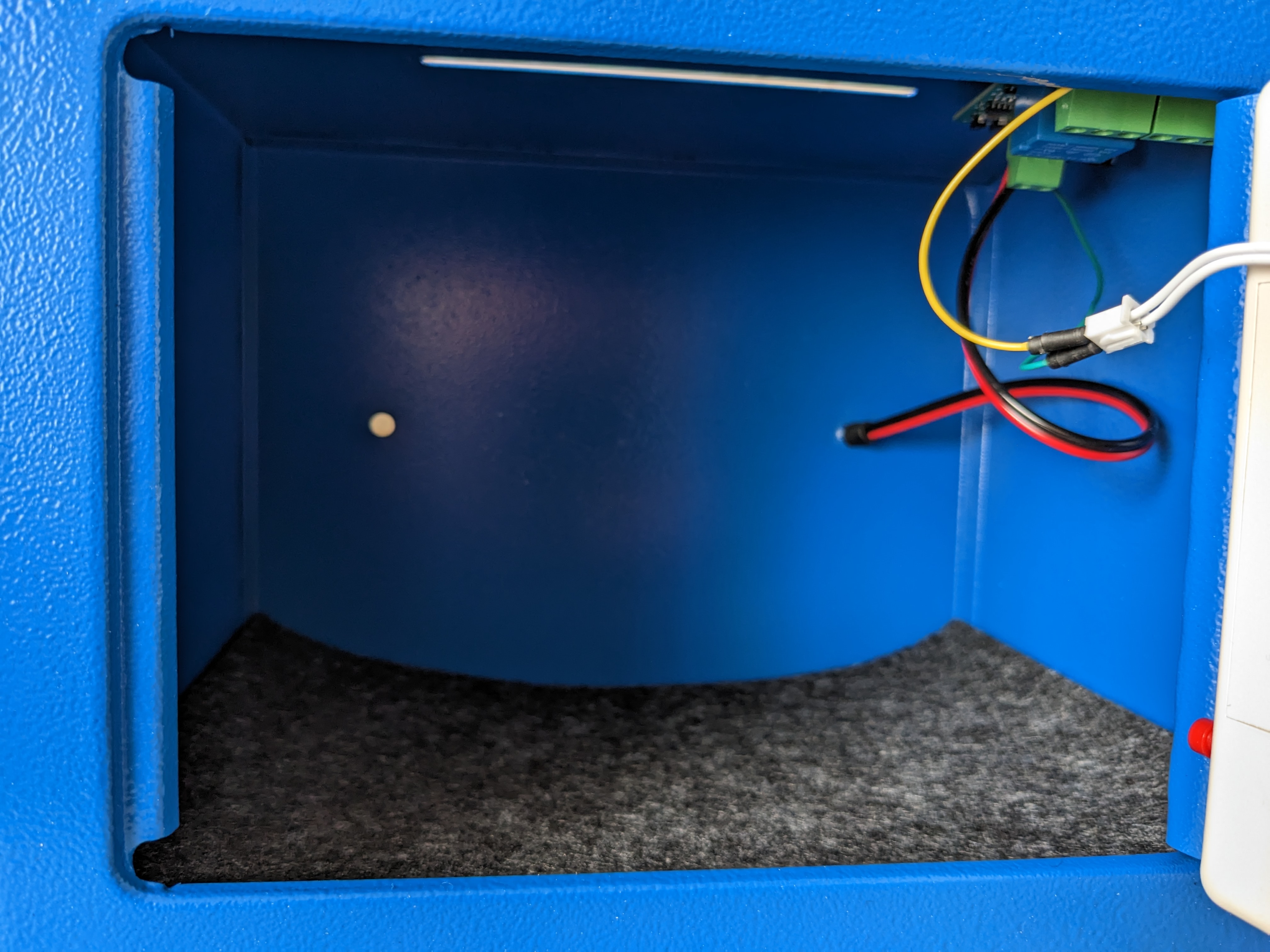
Putting it all together
First I jammed the power cable through one of the mounting holes on the back. This was harder than it should have been because it’s not a panel mount option. And the hole was just a little too small so I stuck a screw driver in and bent the metal slightly to make it bigger.
It still sticks out but it’s good enough.

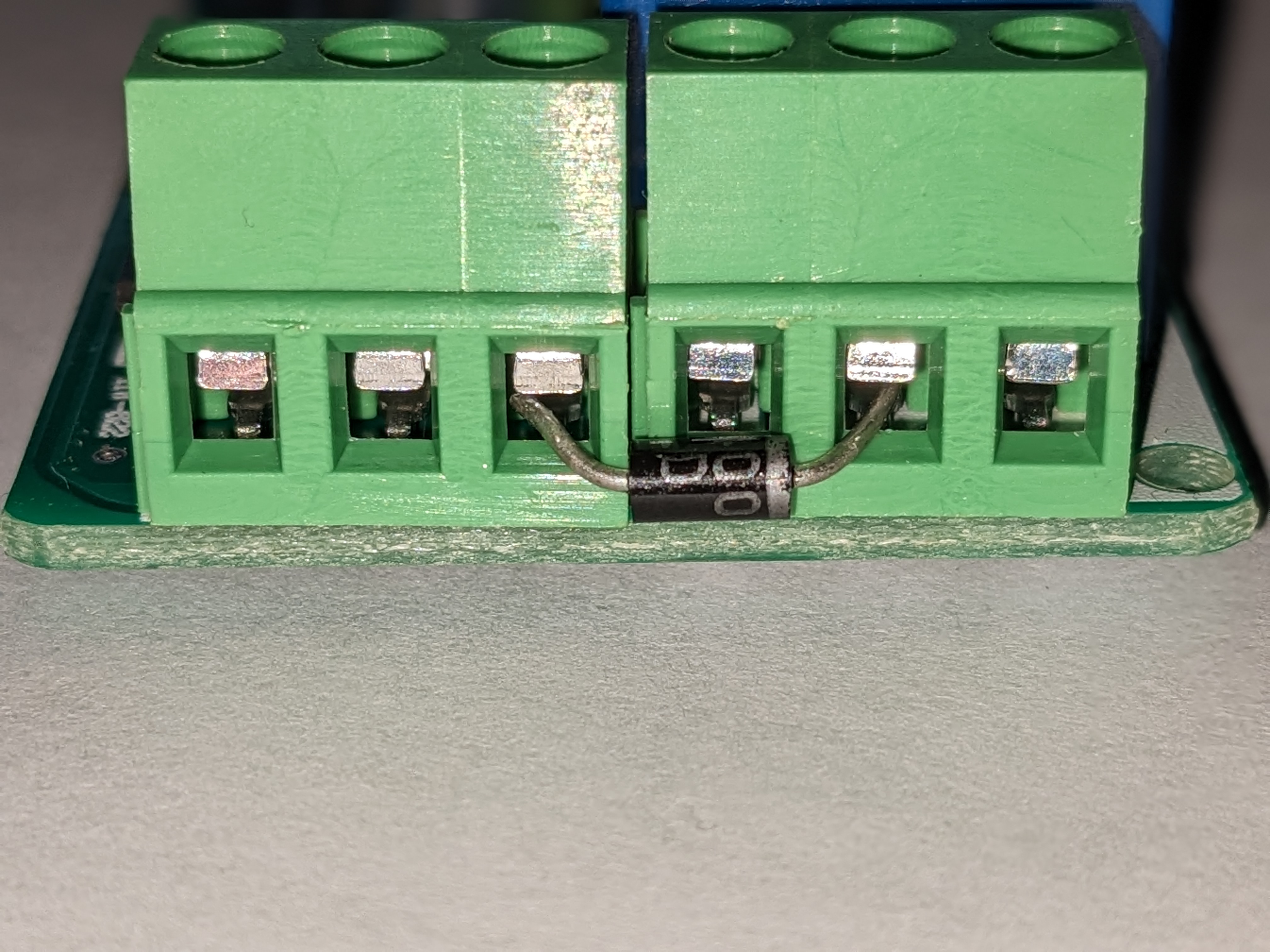
Now we need to add a diode to the output. This is to prevent “back current” from potentially damaging the ESP8266 (when I tried without the diode the board would reboot maybe 1 time out of 3). Almost any diode should work; I used a 1N4001. This needs to connect between the convenient 5V output at the bottom of the “common” on the relay. The stripe side of the diode should be at the relay end.
Now we just need wires going from the negative power at the top of the board and from the far right relay connection at the bottom of the board to go to the solenoid cable.
And that’s really it!
This is what a diagram of the wiring looks like. Did I just scribble something on a piece of paper? Yes, I did!
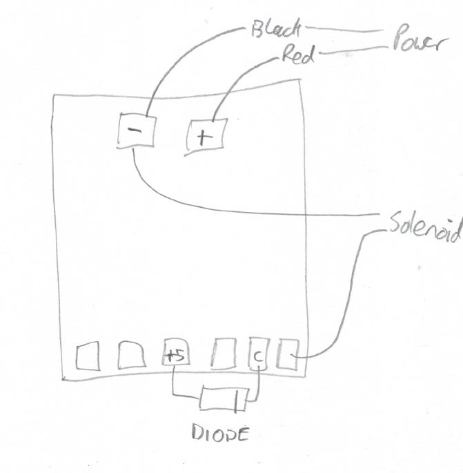
Yeah, there’s two wires going to the negative power; just jam them into the same hole.
To mount this I used some 3mm plastic stick-on standoffs. And I figured I could stick it to the roof of the safe!
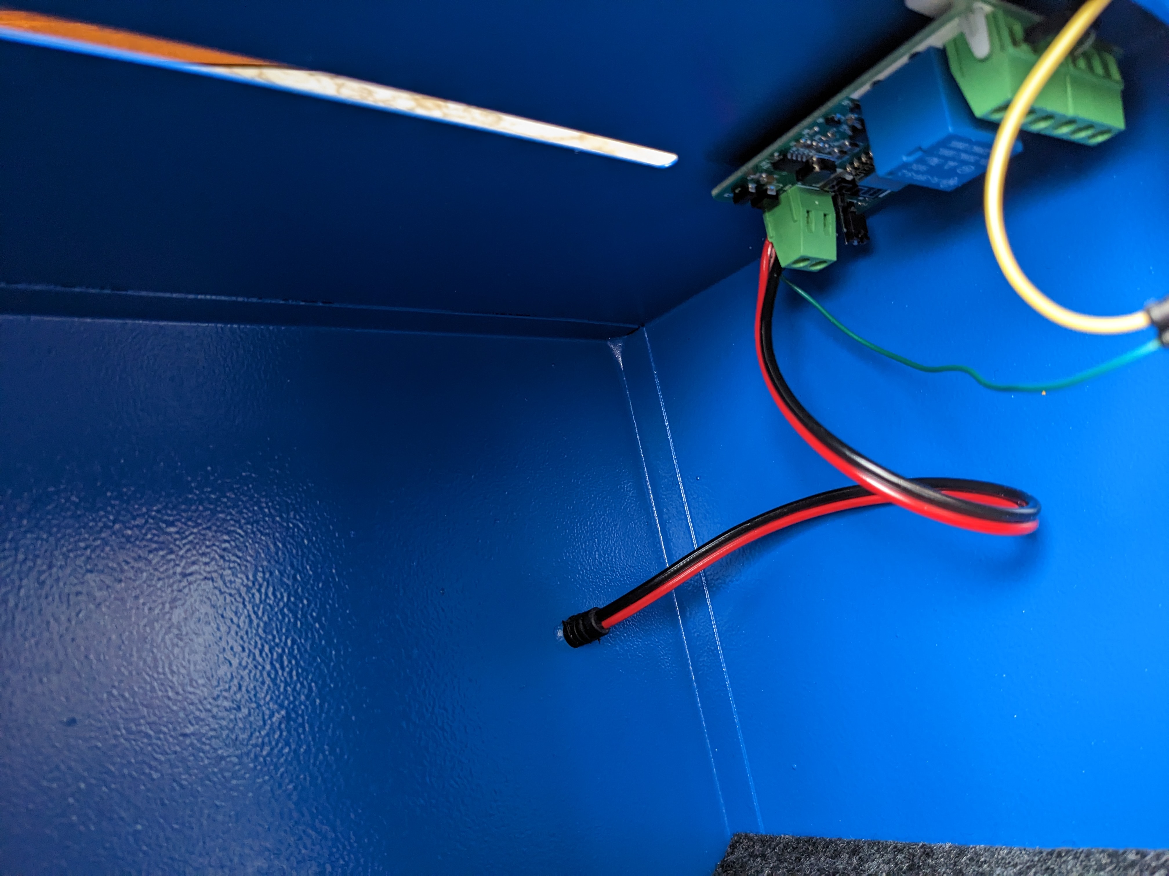
This makes the whole thing very clean.
This is a lot simpler than the v2 build; no soldering, no holding it together with duct tape; just a few wires!
Software
As mentioned, the old software will work; just set it so GPIO 4 is used for the relay.
But we want a timer safe.
The problem I had, here, was in determining the current time. Of course we could just use NTP, but if I wanted to defeat the lock then I’d just set up DHCP to point to a “rogue” time server that claimed it was in the future, and the safe would open. That’s not good.
I realized I didn’t need to save the time, just how long the lock had to run for; time conversions could be done in the browser. Of course we still had to worry about power outages, so every 5 minutes I would save the “time left” into the EEPROM.
Except… Every 5 minutes would be 288 times a day. ESP8266 doesn’t have EEPROM; it emulates it with a fixed space in the flash memory.
I saw that the flash typically has 100,000 write cycles. That means we’re reaching the limit in 347 days; less than a year.
It seems that the SPIFFS (and LittleFS) filesystem that can be used with the ESP8266 has built in wear leveling. Using the 4M1M memory model this allocates 1M to the filesystem. Assuming we use 512 bytes to store data and the meta-data, good wear leveling should means this lasts over 1000 years (if I did the maths right!); at the very least it should exceed the life of the safe.
So that’s what I did; saved the “time left” value in a SPIFFS file.
I then thought I could be clever; why not provide more “fun”… instead of setting an “open time”, why not allow for a time range and pick a value between those times? And for additional uncertainty, why not hide the timer?
Of course time can be added to the safe even when it’s running.
This software can be built with the standard Arduino tool set with the esp8266 libraries loaded. To make it simpler I embed the HTML inside the code (as an include file) rather than using SPIFFS. That way there’s just one image to flash and not two. Yes, we’re using SPIFFS to store time left, but in this way we can update the software easily (even over the network) because it’s just the one image. The code is small enough that it still fits.
The solenoid lock is always kept in the locked position unless the “open” function is selected. Open can not be selected if the timer is still running.
When the safe software is first loaded it will create a WiFi Access Point called something like “Safe-123456” (the exact name will depend on the MAC address of your board). You should connect your phone or laptop to that access point.
This will let you go to http://192.168.4.1 or (if you’re lucky)
http://safe.local and that will display the WiFi configuration
screen.
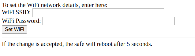
Enter your WiFi SSID and password. In 5 seconds the software will reboot and the safe will connect to your local network. It will attempt to get an address by DHCP.
If it is unable to connect to the network after 60 seconds then it will give up and start up the Safe-123456 access point again and allow you to change the network details and try again.
Once the safe is on your network it will broadcast the name “safe.local” via mDNS (aka zeroconf, Bonjour, Rendezvous). If your machine supports this then you should be able to go to http://safe.local otherwise you may need to check your router to find the IP address that was assigned to it.
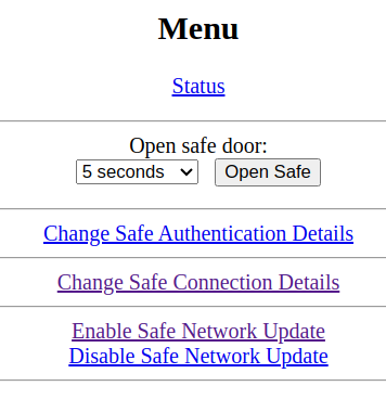
Opening the web page in a browser should give you a menu on the left and a larger status box on the right.
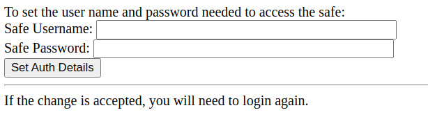
The first thing you should do is go to the “Change Safe Authentication Details” link. Here you can set a username and password for your safe. It’s recommended you do this so that only authorised people on your network can reach this interface. After setting the password you should be prompted to login before doing any more work.
Next you may need to go to the “Safe Connection Details” screen.
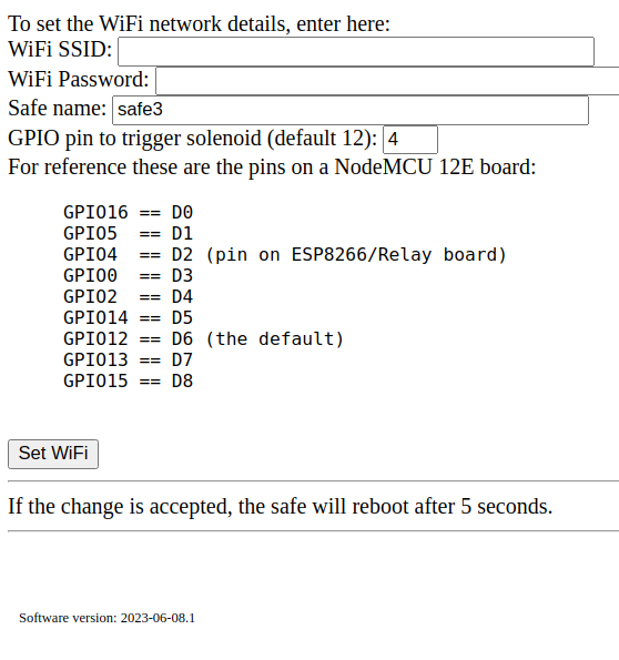
Here is where you can change the WiFi network (if necessary) and the pin the relay is connected to. For the board I’m using in this build this needs to be set to 4 (GPIO4 aka D2). The v2 board used GPIO12 (D6).
Setting the “Safe name” will change the name broadcast via mDNS. So in this example my safe can now be seen at “safe3.local”.
Elsewhere on the menu you’ll see some options:
Open safe” lets you open the solenoid so the door can be opened. This will not work if the safe is locked.
“Enable Safe Network Update” will let you update the firmware remotely, using BasicOTA. If you set a safe password (as recommended above) then the same password is needed for this update. Now you can’t do an update if the safe is locked because then you could just replace the software with one that just always opens the safe!
“Disable Safe Network Update” turns the enable off again
And then the main “Status” screen. This is where the action occurs.
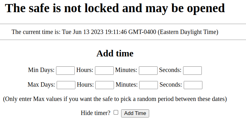
Here you can add time to the safe; if it’s already running a timer then this time will be used to extend the lock. If you just enter a “Min” set of values then this is the time that would be used. If you enter a “Max” then the safe will pick a random time between those two values.
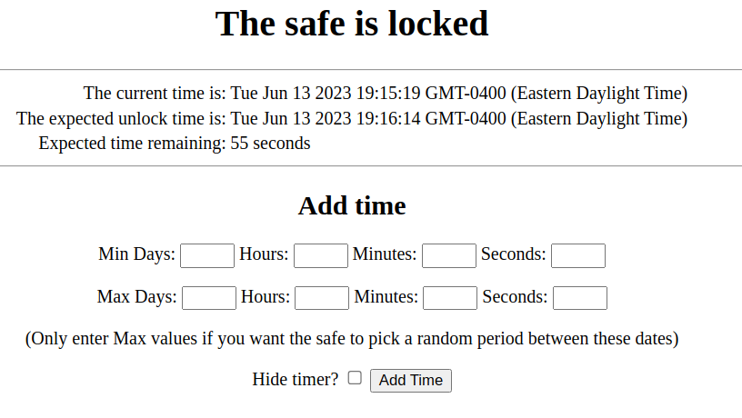
While locked it will tell you when the expected unlock time is, and how long is left.
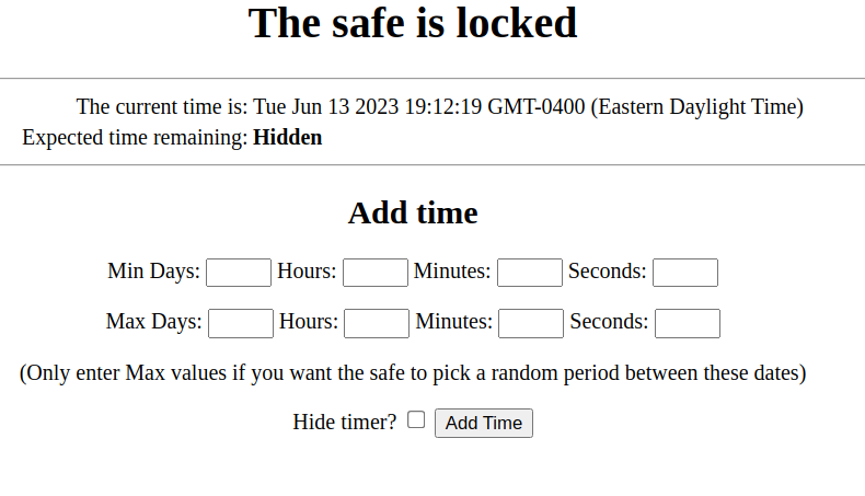
But if you select the “hidden” option then you won’t know…
Conclusion
And that’s it!
The new software is at github
It seems to do what the original Kitchen Safe does, plus more. And possibly cheaper!